
Elastic Grids
- XLogo

Imagine a very elastic grid. Undeformed it appears as a regular lattice of squares. Apply a function and each vertex is deformed from its original position. The grid appears stretched or twisted.
The grid has corner co-ordinate values of [1,1] [1,-1] [-1,-1] [-1,1]
You can alter the mesh size of the grid by changing the
:
Size
varible shown in red in the Go procedure.
You can also comment out one line of code to draw only horizontal or vertical lines.
To
New
# set default screen, pen and turtle values
ResetAll SetScreenSize [400 400] HideTurtle
SetSC Black SetPC Green SetPS 1 PenUp
End
To
GridPos
:
I
:
J
Make "
Rect
Function
:
I
:
J
Output List 180*First
:
Rect
180*Last
:
Rect
End
To
Function
:
X
:
Y
Output List
:
X
:
Y
# unchanged
End
To
Go
New
Make "
Size
19
# increase (eg 29) for finer grid
For [
L
0 1] [
For (List "
I
Minus 1 1 2/
:
Size
) [PenUp
For (List "
J
Minus 1 1 2/
:
Size
) [
If
:
L
=0 [SetPos
GridPos
:
I
:
J
PenDown]
# vertical lines
If
:
L
=1 [SetPos
GridPos
:
J
:
I
PenDown]
# horizontal lines
]]]
End
 Main Command:
Go
Copy and paste to replace the
Function
procedure with one of the following functions which stretch and distort the grid.
Increase the grid Size to
29
for more detail.
To
Function
:
X
:
Y
If
:
X
< 0 [Make "
XSign
Minus 1][Make "
XSign
1]
If
:
Y
< 0 [Make "
YSign
Minus 1][Make "
YSign
1]
Make "
X
Power
:
X
2
Make "
Y
Power
:
Y
2
Output List
:
XSign
*
:
X
:
YSign
*
:
Y
End
To
Function
:
X
:
Y
Make "
X
:
X
+ 0.05 * Sin 360*
:
Y
Make "
Y
:
Y
+ 0.05 * Cos 360*
:
X
Output List
:
X
:
Y
End
Add in the following two procedures which allow the use of polar coordinates to stretch and twist the grid. The first converts polar to rectangular (PtoR), the second rectangular to polar (RtoP) co-ordinates.
To
PtoR
:
RadDist
:
Theta
# convert polar to rectangular co-ordinates
LocalMake "
X
:
RadDist
*Sin
:
Theta
LocalMake "
Y
:
RadDist
*Cos
:
Theta
Output List
:
X
:
Y
End
To
RtoP
:
X
:
Y
# convert rectangular to polar co-ordinates
LocalMake "
Dist
Sqrt ((Power
:
X
2) +(Power
:
Y
2))
If
:
X
<0 [Output List
:
Dist
180 +ATan
:
Y
/
:
X
] [
# else
:
X >0
If
:
Y
<0 [Output List
:
Dist
360 +ATan
:
Y
/
:
X
]
[Output List
:
Dist
ATan
:
Y
/
:
X
]]
# else
:
X =0
If
:
Y
<=0 [Output List
:
Dist
270] [Output List
:
Dist
90]
End
Then, copy and paste to replace the Function procedure with one of the following functions.
To
Function
:
X
:
Y
Make "
Polar
RtoP
:
X
:
Y
Make "
RadDist
First
:
Polar
Make "
Theta
Last
:
Polar
If
:
RadDist
<1 [
Make "
RadDist
Power
:
RadDist
0.4
]
# change 0.4 to 2
Output
PtoR
:
RadDist
:
Theta
End
To
Function
:
X
:
Y
Make "
Polar
RtoP
:
X
:
Y
Make "
RadDist
First
:
Polar
Make "
Theta
Last
:
Polar
If
:
RadDist
<1 [
Make "
Theta
:
Theta
-
100
*(1-
:
RadDist
)]
# change 100 to 200
Output
PtoR
:
RadDist
:
Theta
End
To
Function
:
X
:
Y
Make "
Polar
RtoP
:
X
:
Y
Make "
RadDist
First
:
Polar
Make "
Theta
Last
:
Polar
Make "
RadDist
Power
:
RadDist
0.4
Output
PtoR
:
RadDist
:
Theta
End
Here is an alternative rectangular to polar converter, using trigonometry instead of a second turtle to calculate the angle. It's a bit more mathematical, as ArcTan must be modified for each quadrant. Also, you have to ensure you never divide by zero.
To
RtoP
:
X
:
Y
# convert rectangular to polar co-ordinates
LocalMake "
Dist
Sqrt ((Power
:
X
2) +(Power
:
Y
2))
If
:
X
<0 [Output List
:
Dist
180 +ATan
:
Y
/
:
X
] [
# else
:
X >0
If
:
Y
<0 [Output List
:
Dist
360 +ATan
:
Y
/
:
X
]
[Output List
:
Dist
ATan
:
Y
/
:
X
]]
# else
:
X =0
If
:
Y
<=0 [Output List
:
Dist
270] [Output List
:
Dist
90]
End
- Animation
- Art
- Cellular Auto
- Coding
- Demo
- Dot Plot
- Fractal
- Grid
- Illusion
- L-System
- Multi Turtle
- One Line
- Perspective
- Plane Filling
- Polar
- Puzzle
- Recursion
- Sound
- Spiral
- Spirograph
- Trees
- Walks

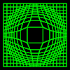
Elastic Grid 1
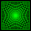
Elastic Grid 2
Book Info

Pages 139-146
Procedures blue
Variables pink
Comments green
Library gray

Visit
XLogo
web site